Masters Capstone Project
Pacific NDT tasked me with designing an overhead powerline inspection system that can take X-ray images of powerline splices and dead-end connectors at various angles. I used this objective to generate an idea for my Masters capstone project.
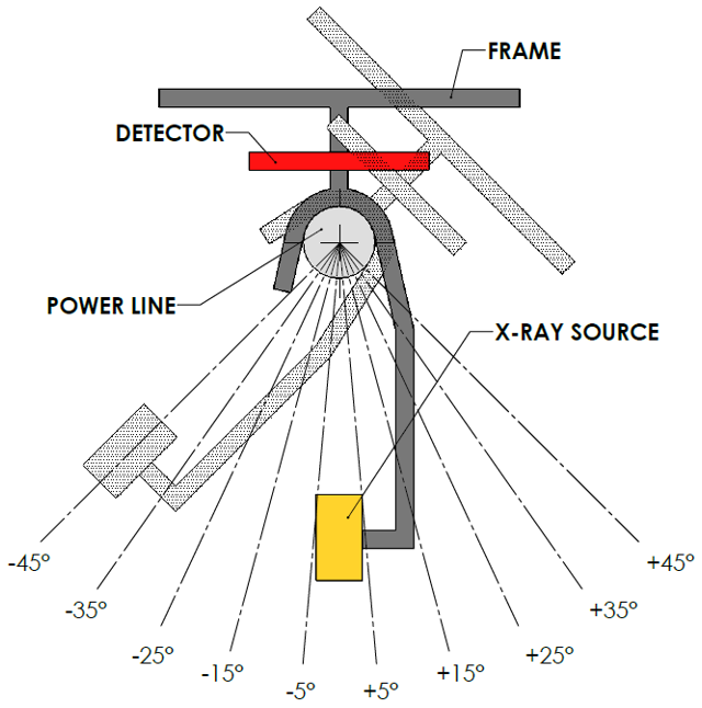
I wanted to leverage an existing frame that I had designed for Pacific NDT months prior. This frame is lightweight and configurable, which made it a great candidate for modification to retrofit a control system. Further, that frame has already been tested and had succeeded in its first mission to image various powerline sections. The ability to image powerline sections at various angles would give this system an improved failure detection sensitivity.

Starting out
My capstone project needed a clear and concise objective, which was the following:
Conceptualize an enhanced solution for X-ray inspection of overhead power lines
Design a control system for a rotating frame, which mounts an X-ray inspection system and allows the capture of multiple images at various angles separated by a fixed interval. Total coverage of 90° (± 45 ° from vertical).
Now with the problem defined, I first had to conceptualize how I would use a control system to rotate the existing frame to different angles. I came up with various ideas but the one that was the most practical was one that I called the linear mass shift (LMS) control system. The name stems from the action that the control system would take to stabilize the frame at a given angle, which is to move a counterbalance on a linear rail that sits on top of the frame.
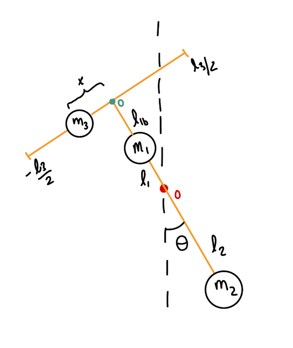
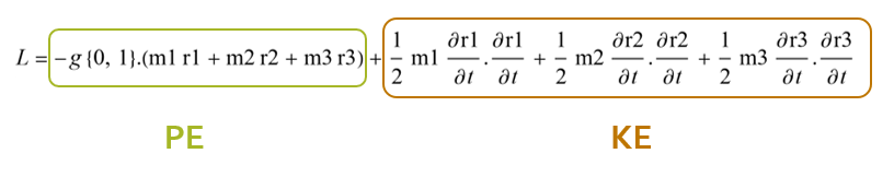
A controller needs full understanding of the dynamics of the system that you are trying to control. As such, I needed to derive the equations of motion governing the frame with an on-board LMS control system. I used the energy method to write the Lagrangian equation for the system, then utilized Wolfram Mathematica to return the Euler-Lagrange differential equations. These equations were also verified manually.


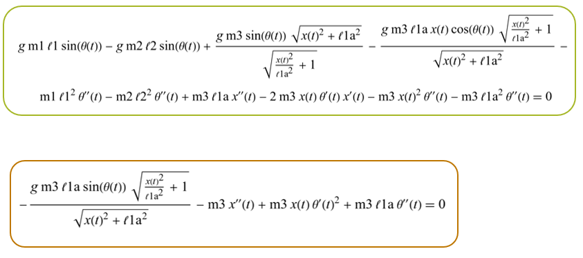
Armed with the equations of motion, I developed a physics simulation of my system. I tested it under various initial conditions and created an animation to visualize the system's dynamics. The model's behavior was consistent with my intuitive predictions of the system's real-world behavior.
Controller Design + Simulation
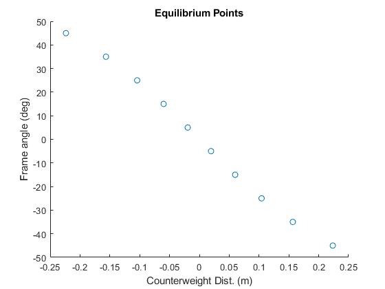
The first challenge I encountered was the limitation of linear controllers. The system I aimed to control was inherently non-linear, making it difficult to use a single controller for the entire range of motion. While searching for solutions, I discovered 'gain-scheduled' controllers. Gain-scheduling leverages linear control theory to approximate non-linear systems. However, it requires multiple linear controllers, each managing a specific segment of the desired trajectory. Every controller needs an operating point, and equilibrium points of the system are usually good choices.
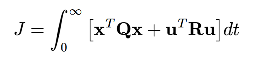
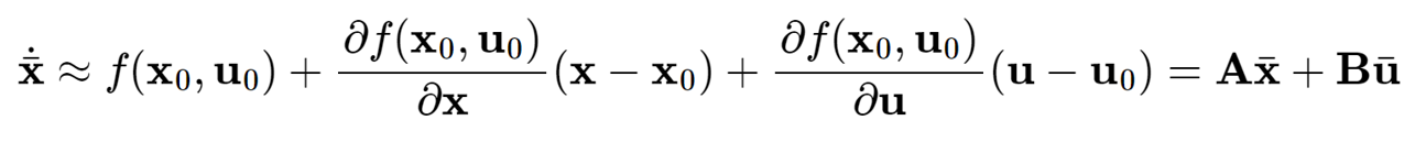
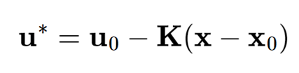
Linear control theory is applicable only to linear systems. Therefore, the next step was to perform a Taylor series expansion of my equations of motion. With a linearized model, I could use a state-space representation of my system to begin designing the controller. I chose an LQR controller for this application and started considering the desired behavior of the controller. The X-ray system captures a single image within 8 seconds but requires approximately 20 seconds to recharge. Consequently, a rapid settling time was not a priority, as the recharge period provided sufficient time. Instead, I opted for a less aggressive controller response to minimize actuator effort, which impacts motor size and overall system weight. I utilized MATLAB for all the controller design work.
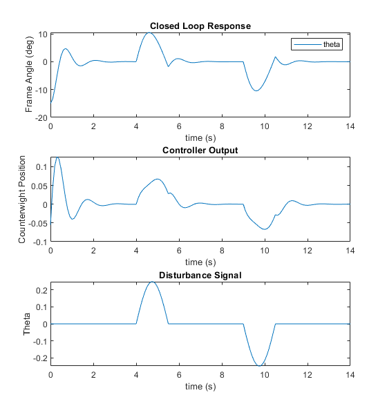
I also wanted to test the robustness of my controller against outside disturbances. Being high off the ground, I expected the powerline inspection system to experience disturbances from wind. I built a Simulink model to showcase that:
The controller works in maintaining the system balanced about the operating point and
That the controller can compensate for disturbances


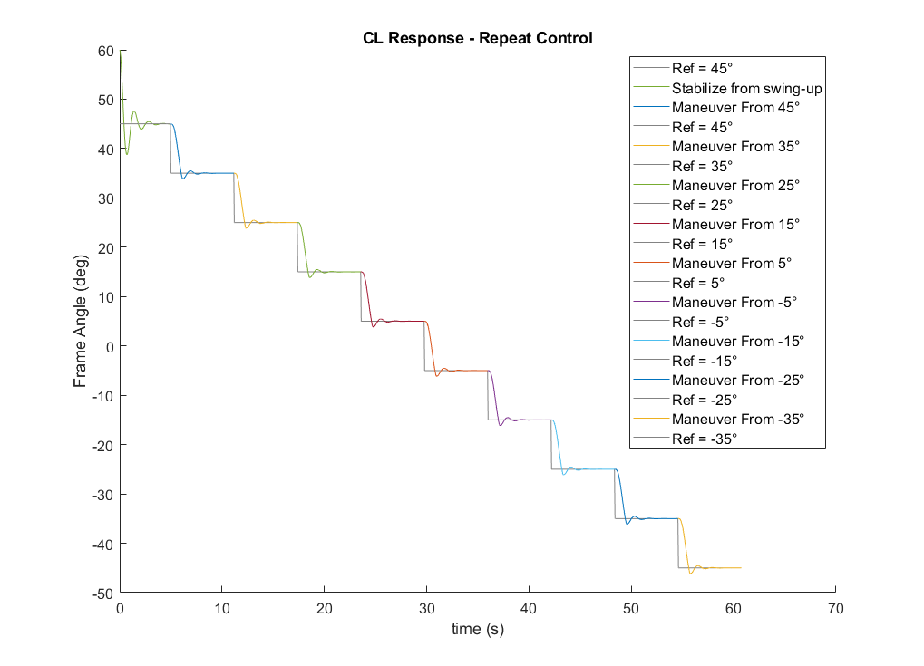
Results
With demonstrated control behavior and acceptable performance (rise time, settling time, and %OS), it was time to stich all the linear controllers to achieve the gain-scheduling over the chosen operating points to cover the entire controlled trajectory from +45° to -45°. The animation below shows the entire trajectory and how the operating points changes over time. Pay close attention to the changing brown circle and dashed line, which indicate the operating point targets for control. This capstone project proved that an LQR could be used to control a powerline inspection system by adding a moving counterbalance to dictate the frame’s angle. Future work can focus on the mechanical design and hardware selection of the control system.