Bolted Flange Joint Analysis
The following is a presentation of my final project for my Masters course in Advanced Computational Methods. I chose to evaluate a bolted flange joint using finite element analysis (FEA).
My background in Chemical Engineering and previous work at Virent's biofuel refinery inspired me to pursue this project. During my time at Virent, I often walked around the research pilot plant, admiring the mechanical engineering efforts that brought the plant to life. Now, as a Mechanical Engineer, I was eager to analyze the most common type of hardware I observed throughout that pilot plant: the bolted flange joint.

Starting out
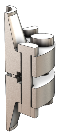
Bolted flange joints serve as the basic nodes of a pipeline system. In a medium-sized refinery, you might find nearly 100,000 bolted flange connections. Leakages in these joints can result in the release of toxic substances into the environment, potentially causing fires or posing risks to humans and wildlife. To properly evaluate a bolted flange joint and avoid these concerns, I first needed to understand the basic components that make up a bolted flange joint. Additionally, I had to learn how a bolted flange joint behaves and identify the metrics that define an acceptable joint.
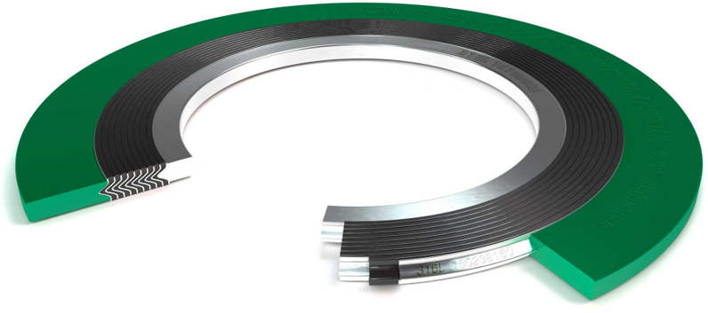
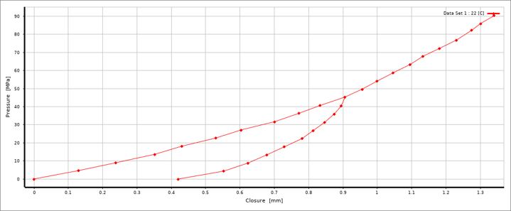
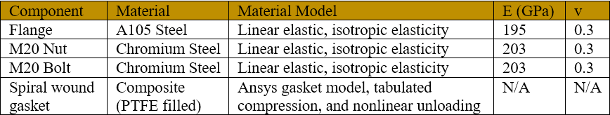
A critical component in the bolted flange joint is the gasket. There are many types of gaskets but one that is popular is the spiral wound composite gasket. This gasket is versatile, allowing a wide range of pressures, temperatures, and chemical exposure - I decided that I would attempt to model one in my FEA for this reason. In my research I also discovered that these gaskets have non-linear loading and unloading behavior, which must be tabulated in ANSYS to simulate real-world behavior.
Based on my research, I knew that to successfully evaluate a bolted flange joint I needed to show in my simulation that:
All elements in the joint must maintain stress levels within their allowable range
The flange rotation is within acceptable range
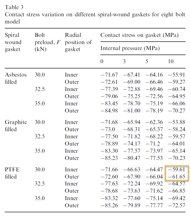
The gasket contact pressure after loading and pressurization is within acceptable range
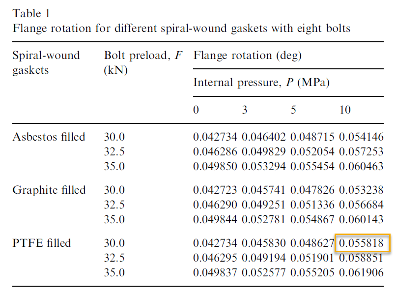
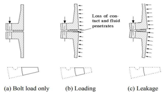
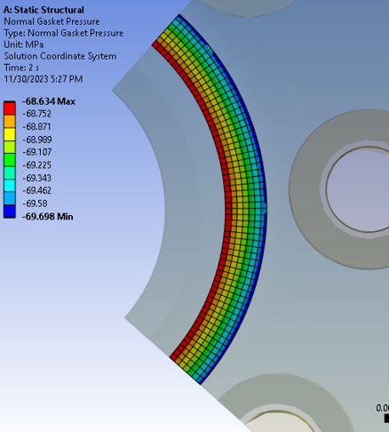
Flange rotation is a critical parameter because it directly affects the residual gasket contact pressure, which must remain within the allowable range to prevent leaks. Flange rotation occurs due to the moment induced by bolt pretension and the system's internal pressure, pivoting around the outer edge of the gasket. Higher rotation values lead to lower contact pressure from the gasket, eventually causing leakage, as demonstrated in the adjacent figure.
FEA
I knew that I wanted to verify my work in the end, and without physical parts to test, my only option was to try to replicate an existing simulation from literature. I chose to replicate the work from Krishna et. al (2007) - the physical properties for the flange, bolts, and spiral would gasket were taken from this paper.
Reference: Murali Krishna, M., M.S. Shunmugam, and N. Siva Prasad. “A Study on the Sealing Performance of Bolted Flange Joints with Gaskets Using Finite Element Analysis.” The International journal of pressure vessels and piping 84, no. 6 (2007): 349–357.

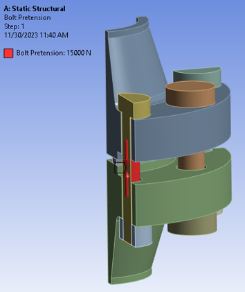
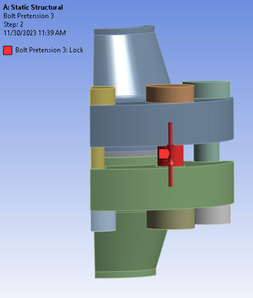
Next, I modeled the geometry in SolidWorks per the mechanical drawings in the Krishna paper. Because of the symmetry in the geometry it was possible to work with a quarter of the model - this decreases the computation time while still having a reliable model.
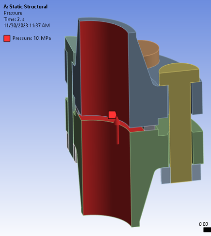
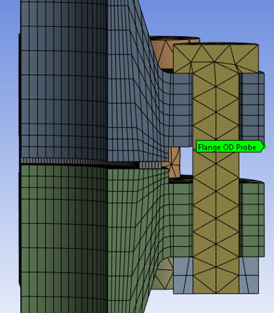
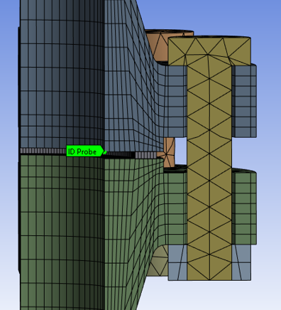
A symmetry boundary condition was applied to the quarter 3D model by selecting the cross-section faces. The hub of the bottom flange was fixed – this was necessary for the assembly to have a datum. Pressure of 10 MPa was added to the inner diameter walls of the flanges, as well as the gap surfaces between both flange faces which would be exposed to the fluid causing the internal pressure. Lastly, a pre-tension of 30 kN was applied to the full bolt whereas only 15 kN of bolt pre-tension was applied to the half-bolt components – this assumption should hold because of the symmetry condition that was applied at the half cross-section of the bolt. The adjacent figures summarize all the boundary conditions that were applied to the bolted flange joint model


Results
The simulation was defined with 2 sperate steps to accurately represent the non-linear, real-world behavior of a composite gasket. The first step is reserved to apply only the bolt pre-tension, then the second step applies the 10 MPa of internal pressure. It is during the second step where I expected to see the gasket lose some compression.
The results of my simulation show that the Von Misses stresses for the bolt and flange were within allowable limits for their respective materials. The flange rotation was calculated to be 0.051°, which is under the allowable rotation for this flange configuration (<3°). Lastly, my gasket contact pressure plot had an expected stress distribution pattern – specifically, higher compressive stress closer to the flange bolt pattern and decreasing contact stress moving towards the inner diameter of the flange. The compressive stress at the worst-case location was 68.6 MPa, which exceeds the required 30 MPa per the ASME standard for this configuration of bolted flange joint.
Based on this information, you can conclude that the flange configuration studied can be used under the specified operating conditions. This is because the bolt and flange stresses were below their acceptable limits, the flange rotation was within acceptable range, and the gasket contact pressure exceeded its lower limit.

I was able to verify my FEA by comparing final results with the Krishna paper, which were in general agreement. My flange rotation value was 8% lower, while my gasket contact pressure values were about 13-15% higher than those obtained by Krishna. These differences could be attributed to different element types chosen for the analysis.
This project provided me with valuable experience in creating a finite element (FE) model to simulate the non-linear behavior of a gasket under real-world conditions. In my literature research, I learned how to test gasket materials to collect the data needed for their application in ANSYS gasket elements. Additionally, I discovered that replicating simulation experiments from research papers and comparing the results with those reported in the articles is an effective strategy for mastering FE modeling techniques of advanced engineering materials.